95 Wyniki
Wyświetl wyniki:
Sortuj według:

W artykule przedstawiono równania wykorzystywane przez program do określenia podpór podporowych na podstawie parametrów słupa.
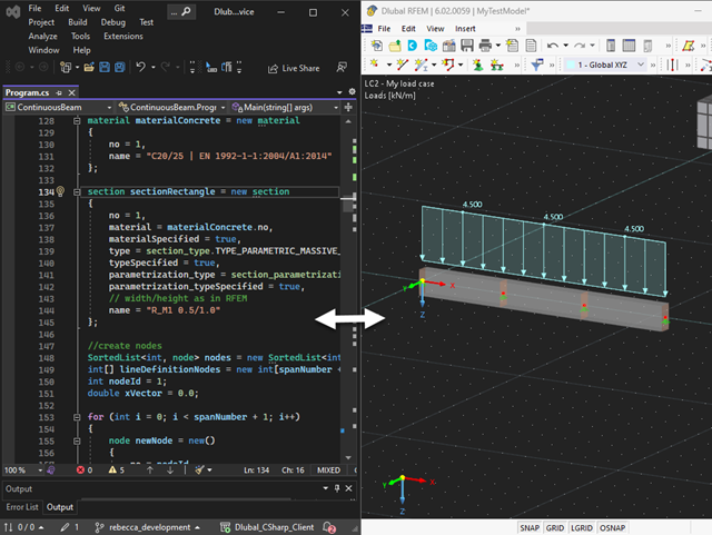
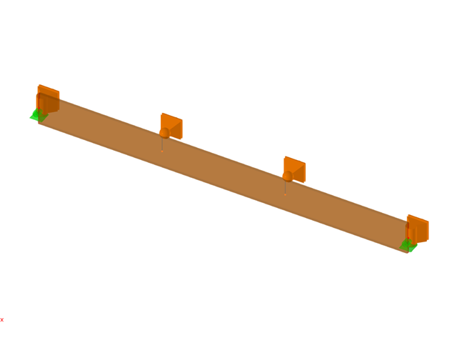
Nasza usługa sieciowa oferuje użytkownikom możliwość komunikacji z programami RFEM 6 i RSTAB 9 za pomocą różnych języków programowania. Funkcje wysokiego poziomu (HLF) firmy Dlubal umożliwiają rozszerzenie i uproszczenie funkcjonalności WebService. Zgodnie z RFEM 6 i RSTAB 9, korzystanie z naszego webservice sprawia, że praca inżyniera jest łatwiejsza i szybsza. Wypróbuj teraz! Ten samouczek pokazuje, jak korzystać z biblioteki C #na prostym przykładzie.
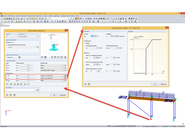
W przypadku analizy stateczności prętów przy użyciu metody pręta zastępczego konieczne jest zdefiniowanie długości wyboczeniowej lub zwichrzenia w celu określenia obciążenia krytycznego dla utraty stateczności. W tym artykule przedstawiono funkcję specyficzną dla programu RFEM 6, za pomocą której można przypisać mimośród do podpór węzłowych, a tym samym wpłynąć na określenie krytycznego momentu zginającego uwzględnianego w analizie stateczności.
Połączenia stalowe w programie RFEM 6 można tworzyć poprzez wprowadzenie wstępnie zdefiniowanych komponentów w rozszerzeniu Połączenia stalowe. Lista tych elementów jest stale rozszerzana, aby ułatwić modelowanie połączeń stalowych. W tym artykule przedstawiamy blachę łączącą, która została niedawno dodana do biblioteki rozszerzenia.
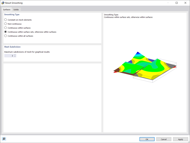
W programie RFEM 6 wyniki dla węzłów siatki ES są określane przy użyciu metody elementów skończonych. Aby rozkład sił wewnętrznych, odkształceń i naprężeń był ciągły, wartości węzłowe są uśredniane w procesie interpolacji. W tym artykule przedstawimy i porównamy różne typy uśredniania, które w tym celu można zastosować.
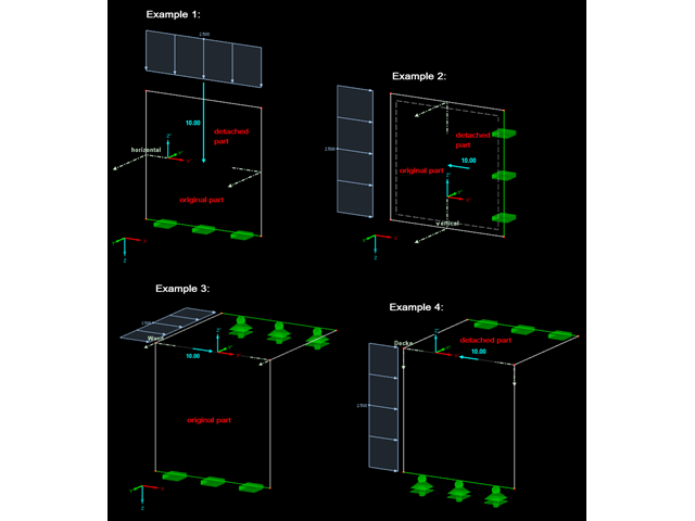
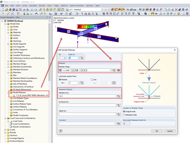
Zwolnienia węzłowe są to specjalne obiekty w programie RFEM 6, które umożliwiają konstrukcyjne odłączenie obiektów dołączonych do węzła. Zwolnienie jest sterowane przez warunki typu zwolnienia, które również mogą mieć właściwości nieliniowe. W tym artykule przedstawiono definicję zwolnień węzłowych na praktycznym przykładzie.
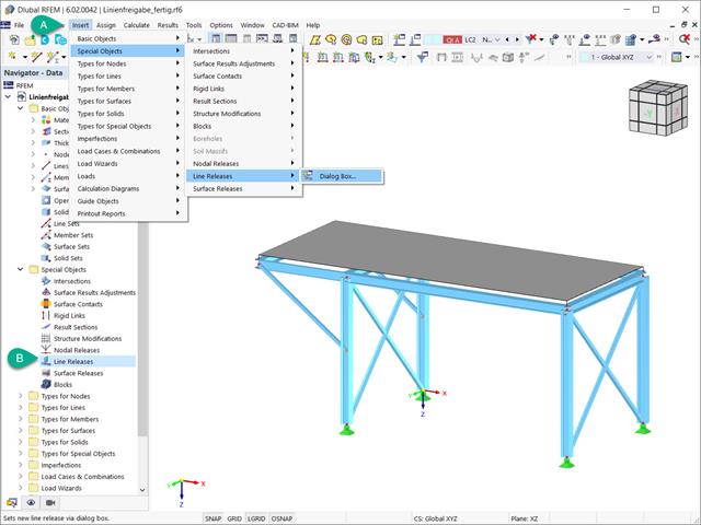
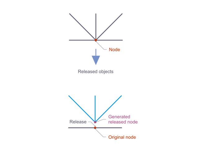
Zwolnienia liniowe to specjalne obiekty w programie RFEM 6, które umożliwiają rozdzielenie konstrukcyjne obiektów połączonych z linią. Stosowane są głównie do oddzielenia dwóch powierzchni, które nie są połączone sztywno lub przenoszą tylko siły ściskające na wspólnej linii granicznej. Poprzez definicję zwolnienia liniowego, w tym samym miejscu generowana jest nowa linia, przenosząca tylko zablokowane stopnie swobody. W niniejszym artykule przedstawiono definicję zwolnień liniowych na przykładzie praktycznym.
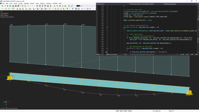
API dla RFEM 6, RSTAB 9 i RSECTION opiera się na koncepcji usług sieciowych (Webservice). Aby zapoznać się z tematem, w poniższym artykule omawiamy kolejny przykład w języku C#.
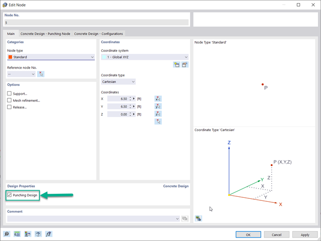
Optymalnym scenariuszem, w którym należy zastosować obliczenia wytrzymałości na przebicie, zgodnie z ACI 318-19 lub CSA A23.3:19, jest sytuacja, w której w płycie występuje duża koncentracja obciążeń lub sił reakcji występujących w jednym węźle. W programie RFEM 6 węzeł, w którym występuje przebicie, nazywany jest węzłem z przebiciem. Przyczyny tak dużej koncentracji sił mogą być spowodowane przez słup, siłę skupioną lub podporę węzłową. Łączenie ścian może również powodować obciążenia skupione na końcach, narożach i na końcach obciążeń liniowych i podpór.
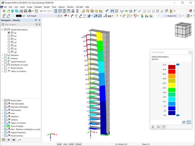
Rozszerzenie Analiza etapów budowy (CSA) umożliwia wymiarowanie konstrukcji prętowych, powierzchniowych i bryłowych w programie RFEM 6 z uwzględnieniem określonych etapów budowy związanych z procesem konstrukcyjnym. Jest to o tyle istotne, że budynki nie powstają w całości od razu, lecz poprzez stopniowe łączenie poszczególnych części konstrukcyjnych. Poszczególne kroki, w których elementy konstrukcyjne oraz obciążenia są dodawane do budynku, nazywane są etapami budowy, podczas gdy sam proces budowy nazywa się procesem konstrukcyjnym.
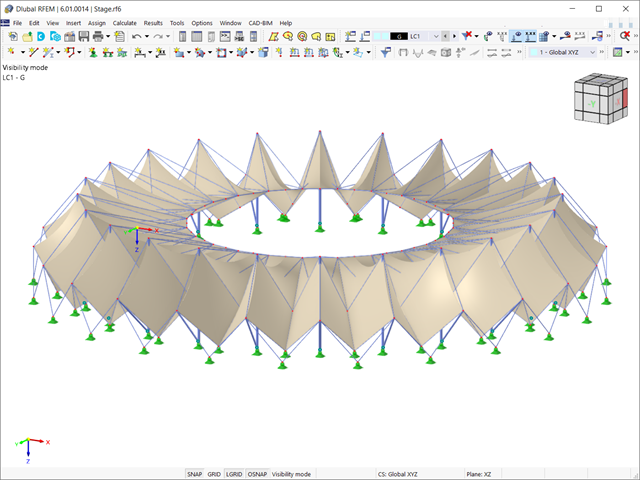
RWIND 2 to program do generowania obciążeń wiatrem w oparciu o CFD (Computational Fluid Dynamics). Symulacja numeryczna przepływu wiatru jest generowana wokół dowolnego budynku, w tym o nieregularnej lub niepowtarzalnej geometrii, w celu określenia obciążenia wiatrem powierzchni i prętów. RWIND 2 może być zintegrowany z programem RFEM/RSTAB w celu przeprowadzenia analizy statyczno-wytrzymałościowej lub jako samodzielna aplikacja.
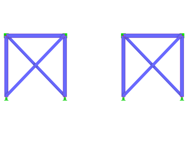
Zdefiniowanie odpowiedniej długości efektywnej ma kluczowe znaczenie dla uzyskania prawidłowej nośności obliczeniowej pręta. W przypadku stężeń krzyżowych, które są połączone w środku, inżynierowie często zastanawiają się, czy pręt należy rozciągnąć na całej jego długości, czy też wystarczy użyć połowy długości w miejscu połączenia prętów. W tym artykule przedstawiono zalecenia AISC i pokazano, jak określić efektywną długość stężeń krzyżowych w programie RFEM.
Obliczenia na przebicie zgodnie z EN 1992-1-1 należy przeprowadzić dla płyt poddanych obciążeniu skupionemu lub reakcji. Węzeł, w którym przeprowadzana jest analiza nośności na przebicie (tj. w miejscu, w którym występuje problem z przebiciem) nazywany jest węzłem odporności na przebicie. Obciążenie skupione w tych węzłach może zostać wprowadzone przez słupy, siłę skupioną lub podpory węzłowe. Koniec przyłożenia obciążenia liniowego na płyty również jest traktowany jako obciążenie skupione, dlatego należy również kontrolować nośność na ścinanie na końcach, narożach i końcach ścian oraz na końcach lub narożach obciążeń liniowych i podpór liniowych.

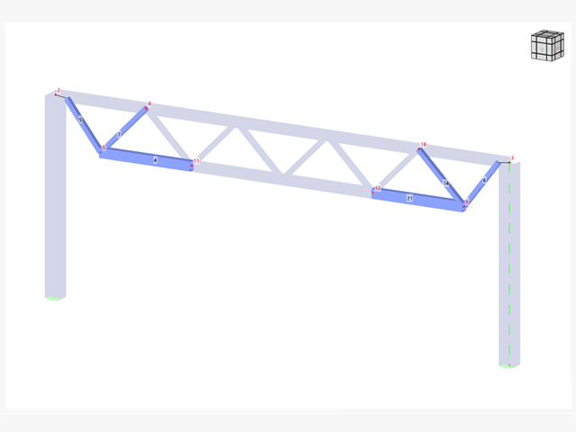
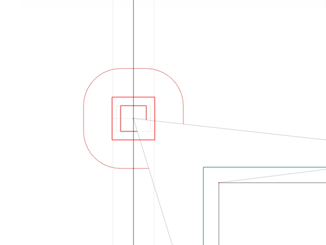
Sprawdzenie stateczności dla wymiarowania prętów zastępczych zgodnie z EN 1993-1-1, AISC 360, CSA S16 i innymi normami międzynarodowymi wymaga uwzględnienia długości obliczeniowej (tj. efektywnej długości prętów). W programie RFEM 6 długość efektywną można określić ręcznie, przypisując podpory węzłowe i współczynniki długości efektywnej lub, z drugiej strony, poprzez import z analizy stateczności. Obie opcje zostaną przedstawione w tym artykule poprzez określenie efektywnej długości słupa obramowanego na rysunku 1.

W tym artykule opisano, w jaki sposób płaska płyta budynku mieszkalnego jest modelowana w programie RFEM 6 i wymiarowana zgodnie z Eurokodem 2. Płyta ma grubość 24 cm i jest podparta na słupach o długości 45/45/300 cm w rozstawie co 6,75 m (rysunek 1). Słupy są modelowane jako sprężyste podpory węzłowe poprzez zdefiniowanie sztywności sprężystej na podstawie warunków brzegowych (rysunek 2). Jako materiały wybrano beton C35/45 i stal zbrojeniową B 500 S (A).
Konstrukcje tymczasowe, takie jak rusztowania lub rozpory, są konstrukcjami o wszechstronnym zastosowaniu, które można bardzo dobrze dostosować do różnych warunków geometrycznych na budowie.
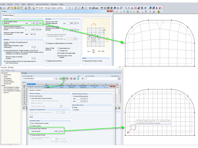
Podczas modelowania i wymiarowania tafli szkła w RF-GLASS istnieją dwie różne opcje ustawień siatki ES.
In RFEM gibt es die Möglichkeit, sich die Resultierende eines Schnittes beziehungsweise einer Freigabe ausgeben zu lassen. In diesem Beitrag soll geklärt werden, auf welchen Teil der Schnittfläche diese wirkt. Am einfachsten wäre es, die Resultierende auf ein Schnittufer der Fläche zu beziehen. Da jedoch ein Schnitt auch durch mehrere Flächen mit unterschiedlichen lokalen Koordinatensystemen verlaufen kann, ist die Aussage mittels Schnittufer nicht möglich.
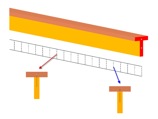
Neben dem genormten Gamma-Verfahren lassen sich nachgiebig verbundene Träger auch als Stabwerksmodell abbilden.
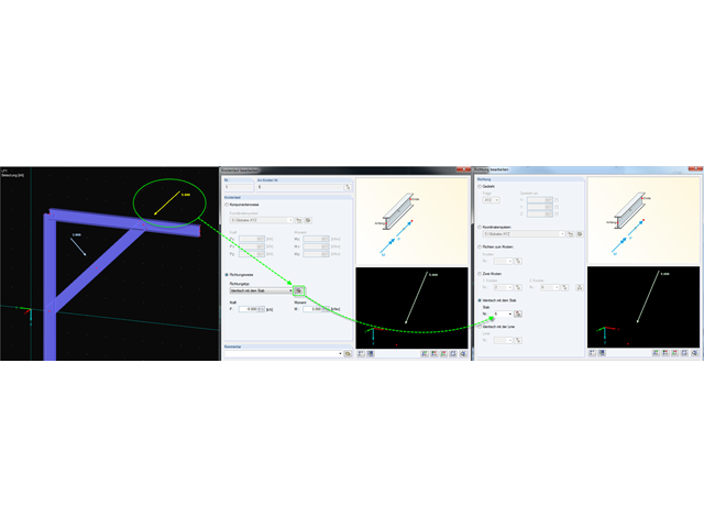
In RFEM und RSTAB stehen verschiedene Optionen zur Eingabe von Knotenlasten zur Verfügung. Durch diese implementierten Features wird es dem Anwender ermöglicht, die Knotenlasten bezogen auf verschieden Komponenten im Raum zu definieren.
Ab und zu muss in einem Modell berücksichtigt werden, dass einige Träger ohne Verschraubung und ohne Schweißnaht nur lose aufeinander liegen.
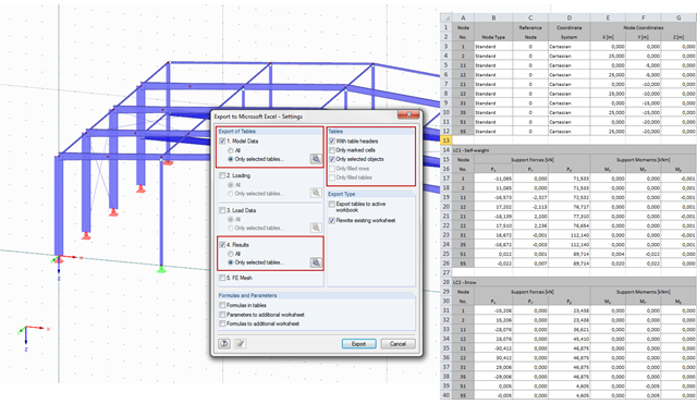
W programach RFEM i RSTAB można eksportować wyniki obliczeń do dokumentu Excel.
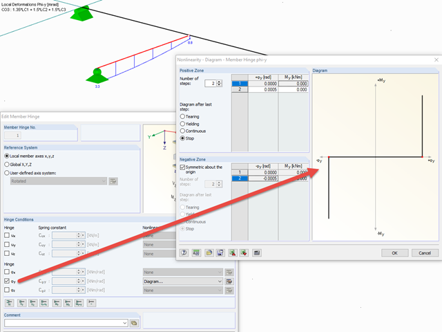
Aby przeprowadzić symulację luzu podporowego w połączeniu między prętami, można użyć funkcji "Wykres" dla zwolnień pręta. Aby skorzystać z tej funkcji, należy najpierw zdefiniować odpowiedni stopień swobody jako zwolnienie. Następnie z rozwijanej listy można wybrać funkcję "Wykres".

In RF-/STAHL EC3 können gleichzeitig mehreren Stäben beziehungsweise Stabsätzen dieselben Eingabedaten zugewiesen werden. Die gleichzeitige Zuweisung der Eingabedaten ist für Zwischenabstützungen, effektive Längen, Knotenlager, Stabendgelenke sowie Schubfeld und Drehbettung möglich.
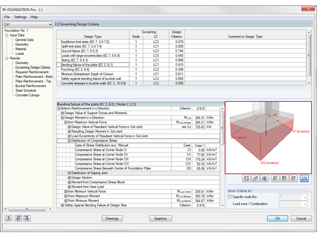
In RF-/FUND Pro steht dem Anwender eine grafische Ausgabe der Ergebnisdetails zur Verfügung. Hierzu muss nach der Berechnung zur Maske "2.2 Maßgebende Kriterien" gewechselt werden. In der interaktiven Grafik dieser Maske können zu jedem geführten Nachweis einzelne bemessungsrelevante Werte dargestellt werden.
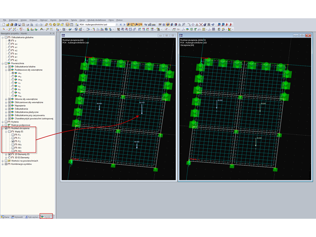
In RFEM steht dem Anwender bei der Ergebnisauswertung die Lastverteilung zur Verfügung.
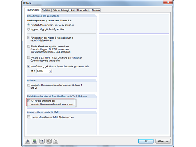
In der EN 1993-1-1 wurde mit dem Allgemeinen Verfahren ein Nachweisformat für Stabilitätsnachweise eingeführt, welches sich für ebene Systeme mit beliebigen Randbedingungen und veränderlicher Bauhöhe anwenden lässt. Die Nachweise können für eine Belastung in der Haupttragebene und gleichzeitiger Druckbeanspruchung geführt werden. Dabei werden die Stabilitätsfälle Biegedrillknicken und Biegeknicken aus der Haupttragebene heraus, also um die schwache Bauteilachse, nachgewiesen. Häufig stellt sich daher die Frage, wie in diesem Zusammenhang Biegeknicken in der Haupttragebene nachgewiesen werden kann.
Modell- und Lastobjekte können nicht nur grafisch oder tabellarisch definiert, sondern auch über Parameter erzeugt werden (siehe Handbuch). Bei dieser parametrisierten Eingabe kann auch auf Zellen bestimmter Tabellen des Programms zugegriffen werden. Auf diese Weise lässt sich beispielsweise ein Lastparameter mit einem Modelldatenparameter verknüpfen. Die Referenz wird dabei durch das $-Zeichen hergestellt.
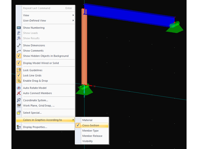
Zur übersichtlicheren Darstellung der Struktur ist es möglich, diese in verschiedenen Farben darzustellen. Die entsprechende Auswahl kann über einen Klick mit der rechten Maustaste in das Arbeitsfenster aufgerufen werden.
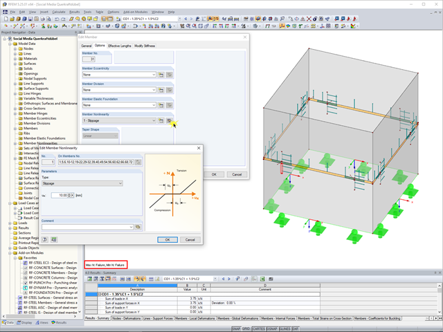
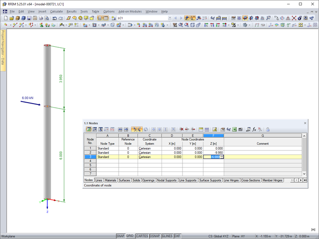
Program RFEM 5 umożliwia wykorzystanie wielu różnych nieliniowości prętowych do wymiarowania modelu. W poniższym tekście przyjrzymy się przykładowi wykorzystania nieliniowości pręta typu „poślizg”. Przykładem jest uproszczony model włazu betonowego w rzucie kwadratowym.